miércoles, 14 de septiembre de 2022

Fortiweb

Control de aplicaciones expuestas a internet

Control de APIS


one-arm, una sola red

two-arm dos redes distintas


4 Pasos generales para la configuración inicial.

    1.Cargar el certificado

            extensiones  

                .prt

                .pm

    2. Configurar el server pool,  la ip del server que contiene la aplicaciones web

    3. Configurar el virtual server, una ip dentro de la red del Fortiweb.

    4. Configurar política 


Capas de protección

ip reputacion

ddos proteccion

protocol validation

attack signatures

antivirus/dlp

integration

advance proteccion

behavioral validation

https://avinetworks.com/glossary/ssl-offload/


Web Application Firewall or WAF provides web application security for online services from malicious Internet traffic. WAFs detect and filter out threats such as OWASP Top 10 which could degrade, compromise or bring down online applications.

SSL offloading is the process of removing the SSL based encryption from incoming traffic that a web server receives to relieve it from decryption of data. Security Socket Layer (SSL) is a protocol that ensures the security of HTTP traffic and HTTP requests on the internet. SSL traffic can be compute intensive since it requires encryption and decryption of traffic. SSL (called TLS or Transport Layer Security now) relies on public key cryptography to encrypt communications between the client and server sending messages safely across networks. Encryption of sensitive information protects against potential hackers and man-in-the-middle attacks.
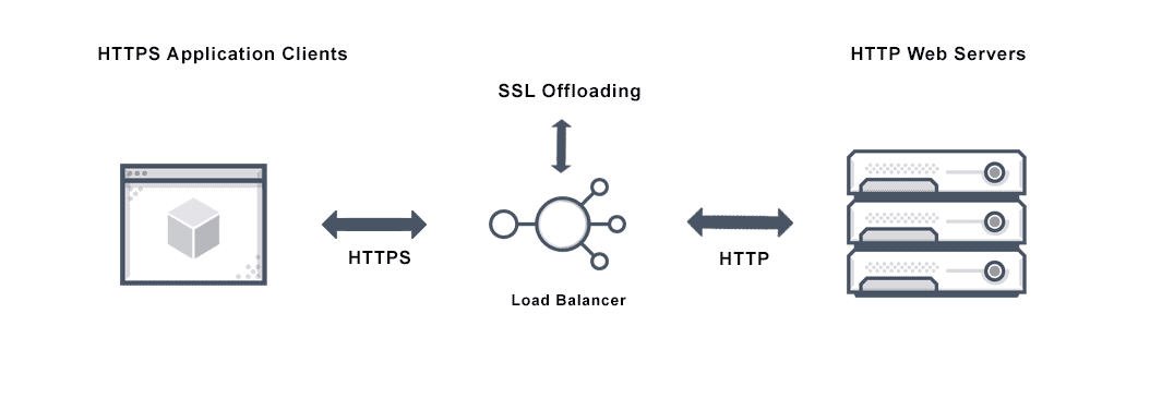
Image depicting ssl offloading through a load balancer that ensures security of http to https traffic from applications to webservers.


-------------------


troubleshooting

26:12:6

26 access control
12 politica
6 recipient policy


lunes, 2 de agosto de 2021

Forticlient (FCT) debug

 Desde el FGT:

diagnose vpn ssl debug-filter src-addr4 x.x.x.x --> donde x.x.x.x es la IP Pública del cliente que realiza la prueba.
diagnose debug application sslvpn -1
diagnose debug application fnbamd -1
diagnose debug enable

Desde el FCT:
How to enable debug log in FortiClient v5.0 and later
https://kb.fortinet.com/kb/documentLink.do?externalID=FD38644


Para detener la captura del FGT:
diagnose debug disable
diagnose debug reset

jueves, 7 de mayo de 2020

Filtro

diagnsose sys session filter src
diagnose sys session list | grep policy_id

diagnose sys session filter dport  5060
 show | grep -f Red\ server

diagnose ip addres lists

domingo, 3 de mayo de 2020

INSPECCIÓN AVANZADA DE FLUJO DE TRÁFICO

INSPECCIÓN AVANZADA DE FLUJO DE TRÁFICO

diagnose debug disable
diagnose debug flow trace stop
diagnose debug flow filter clear
diagnose debug flow show function-name disable
diagnose debug flow show iprope disable
diagnose debug reset 4
diagnose debug flow filter dadd 8.8.8.8
diagnose debug flow filter sadd 10.212.134.200
diagnose debug flow show console enable
diagnose debug console timestamp enable
diagnose debug enable
diagnose debug flow trace start 30

sábado, 2 de mayo de 2020

Fortigate SIP


https://help.fortinet.com/fos50hlp/56/Content/FortiOS/fortigate-voip-guide/ALG.htm
https://help.fortinet.com/fos60hlp/60/Content/FortiOS/fortigate-voip-guide/ALG.htm
https://kb.fortinet.com/kb/documentLink.do?externalID=FD38920


Fortigate maneja dos métodos para controlar las sesione SIP


The SIP session helper

config system settings
set default-voip-alg-mode kernel-helper-based
set sip-helper enable
end


show system session-helper
.
.
.
edit 13
set name sip
set port 5060
set protocol 17
next


Use the following command to set the debug level for the SIP session helper. Different debug masks display different levels of detail about SIP session helper activity.
diagnose sys sip debug-mask <debug_mask_int>
Use the following command to display the current list of SIP dialogs being processed by the SIP session help. You can also use the clear option to delete all active SIP dialogs being processed by the SIP session helper.
diagnose sys sip dialog {clear | list}
Use the following command to display the current list of SIP NAT address mapping tables being used by the SIP session helper.
diagnose sys sip mapping list
Use the following command to display the current SIP session helper activity including information about the SIP dialogs, mappings, and other SIP session help counts. This command can be useful to get an overview of what the SIP session helper is currently doing.
diagnose sys sip status

The SIP session helper is disabled by default and must be enabled for the SIP session helper to process VoIP traffic

The SIP ALG

config system settings
set default-voip-alg-mode proxy-based
set sip-helper disable
end


config voip profile
    edit "default"
        set comment "Default VoIP profile."
    next

By default all SIP traffic is processed by the SIP ALG. If the policy that accepts the SIP traffic includes a VoIP profile, the SIP traffic is processed by that profile. If the policy does not include a SIP profile the SIP traffic is processed by the SIP ALG using the default VoIP profile.

Use the following command to list all active SIP calls being processed by the SIP ALG. You can also use the clear option to delete all active SIP calls being processed by the SIP ALG, the idle option to list idle SIP calls, and the invite option to list SIP invite transactions.
diagnose sys sip-proxy calls {clear | list | idle | invite}
Use the following commands to employ filters to display specific information about the SIP ALG and the session that it is processing. You can build up a filter by including a number of options such as source address, VoIP profile, policy, and so on.
diagnose sys sip-proxy filter <filter_options>
diagnose sys sip-proxy log-filter <filter_options>
Use the following command to display the active SIP rate limiting meters and their current settings.
diagnose sys sip-proxy meters list
Use the following command to display status information about the SIP sessions being processed by the SIP ALG. You can also clear all SIP ALG statistics.
diagnose sys sip-proxy stats {clear | list}


Conflicts between the SIP ALG and the session helper

------------

diagnose sys sip status
dialogs: max=32768, used=0
mappings: used=0
dialog hash by ID: size=2048, used=0, depth=0
dialog hash by RTP: size=2048, used=0, depth=0
mapping hash: size=2048, used=0, depth=0
count0: 0
count1: 0
count2: 0
count3: 0
count4: 0
This command output shows that the session helper is not processing SIP sessions because all of the used and count fields are 0. If any of these fields contains non-zero values then the SIP session helper may be processing SIP sessions.


diagnose sys sip-proxy stats list 


The RTP port number is included in the m= part of the SDP profile. In the example above, the SIP INVITE message includes RTP port number is 49170 so the RTCP port number would be 49171. In the SIP response message the RTP port number is 3456 so the RTCP port number would be 3457.


Debug:
 diagnose debug disable 
 diagnose debug reset
 diagnose debug application sip -1
 diagnose debug enable
Use following commands to display status information about the SIP sessions being processed by the SIP ALG.
Clear all SIP ALG statistics.

 diagnose sys sip-proxy calls list
 diagnose sys sip-proxy stats {clear | list}
 diagnose sys sip-proxy stats
 diagnose sys sip status
 diagnose sys sip dialog list
 diagnose sys sip mapping list


-
diagnose debug application sip 

1Configuration changes, mainly addition/deletion/modification of virtual domains.
2TCP connection accepts or connects, redirect creation.
4Create or delete a session.
16Any IO read or write.
32An ASCII dump of all data read or written.
64Include HEX dump in the above output.
128Any activity related to the use of the FortiCarrier dynamic profile feature to determine the correct profile-group to use.
256Log summary of interesting fields in a SIP call.
1024Any activity related to SIP geo-redundancy.
2048Any activity related to HA syncing of SIP calls.

miércoles, 11 de julio de 2018

Notas de HA en Fortigate


Validar si el cluster esta sincronizado

diagnose sys ha checksum cluster

diagnose sys ha checksum recalculate

execute ha synchronice star  ==> este comando lo utilizo en la unidad de backup para sincronizar la configuración de la unidad primaria a la secundaria.

##################################
########### HA_PRIMARY ###########
##################################
config system global
  set hostname Primary_FortiGate
end
config system ha
  set mode a-p
  set group-name My-HA-Cluster
  set password
  set priority 250
  set override enable
  set hbdev ha1 50 ha2 50
end
#################################
########### HA_BACKUP ###########
#################################
execute factoryreset
config system global
   set hostname Backup_FortiGate
end
config system ha
   set mode a-p
   set group-name My-HA-Cluster
   set password
   set priority 50
   set hbdev ha1 50 ha2 50
end
#########################################################################
########### Checking cluster operation and disabling override ###########
#########################################################################
diag sys ha cluster-csum
config system ha
    set override disable
end
OVERRIDE  funciona como un premt , el primario siempre seria el primario en condiciones normales.


///////////
diagnose sys ha reset-uptime
//////////

martes, 10 de julio de 2018

Buscar en Fortinet


show full-configuration | grep -f

este comando nos sirve para encontrar un elemento en la configuración de nuestro firewall  mostrándonos la sección completa, por ejemplo si buscamos una ip nos muestra que esta en un firewall address y sus atributos.

sh full-configuration | grep -f 10.10.10.10
config firewall address
    edit "direccion_ip"
        set type ipmask
        set comment ''
        set visibility enable
        set associated-interface ''
        set color 0
        set allow-routing disable
        set subnet 10.10.10.10 255.255.255.255 <---
    next
end

jueves, 20 de abril de 2017

Sincronizar un nodo a cluster

En ocaciones se requiriere realizar el cambio de un firewall en un cluster por diferentes razones, la principal por daño en alguno de estos. para poder sincronizar la configuración inicialmente pensé que copiar la misma en el nodo nuevo seria la forma adecuada sin embargo con apoyo de un amigo me mostró como era la manera indicada de realizar el procedimiento minimizando problemas en este. 

Inicialmente el nodo nuevo debe ser actualizado a la versión que tenga el nodo activo.
Para adelantar lo requerido validamos en el nodo activo el numero que se le asigno al cluster id, y no es por defecto debemos validarlo, esto lo hacemos con el siguiente comando:

UUUUU@XXXX> show chassis cluster status 
Monitor Failure codes:
    CS  Cold Sync monitoring        FL  Fabric Connection monitoring
    GR  GRES monitoring             HW  Hardware monitoring
    IF  Interface monitoring        IP  IP monitoring
    LB  Loopback monitoring         MB  Mbuf monitoring
    NH  Nexthop monitoring          NP  NPC monitoring              
    SP  SPU monitoring              SM  Schedule monitoring

######Cluster ID: 3#####
Node   Priority Status         Preempt Manual   Monitor-failures

  
En este momento podemos continuar con el nodo nuevo asi:

 -Borramos la configuración

root# delete
This will delete the entire configuration
Delete everything under this level? [yes,no] (no) yes

-Configuramos una contraseña de root

root# set system root-authentication plain-text-password
New password:
Retype new password:

 -  Guardamos la configuración
       
 root# commit  

-Salimos del modo de configuración

root# exit  
Exiting configuration mode

root> 

-Configuramos el id del cluster y en numero del nodo que vamos a reemplazar.

root> set chassis cluster cluster-id 3 node 1
warning: A reboot is required for chassis cluster to be enabled

 - Apagamos el firewall, realizamos la conexión del cableado de red , al finalizar y estar seguros del cableado procedemos a encender el firewall.

Validamos el estado del cluster para el RD de sincronizacion entre los firewall, generalmente el Redundancy group 0 , una vez el cluster esta sincronizado primario y secundario en modo de configuración hacemos un commit full y listo!!! Y tenemos la configuraracion en en los dos nodos.

viernes, 19 de febrero de 2016

JNP: USO DE ROUTING INSTANCE – FORWARDING


JNP: USO DE ROUTING INSTANCE – FORWARDING


Esta opción sirve básicamente para enrutar tráfico dependiendo del origen del mismo.

El primer paso es definir un filtro para elegir los orígenes que queremos enrutar.

Definimos una instancia de enrutamiento utilizando la funcionabilidad de Forwarding*  (instance-type)[1] y configuramos la ip o red destino.


set routing-instances RI-DSO-WEB instance-type forwarding
set routing-instances RI-DSO-WEB routing-options static route X.X.X.X/32 next-hop Y.Y.Y.Y


[1] type—Can be one of the following:
·         evpn—(MX 3D Series routers only) Enable an Ethernet VPN (EVPN) on the routing instance. You cannot configure the evpn option under the [edit logical-systems logical-system-namerouting-instances routing-instance-name instance-type] hierarchy level.
·         forwarding—Provide support for filter-based forwarding, where interfaces are not associated with instances. All interfaces belong to the default instance. Other instances are used for populating RPD learned routes. For this instance type, there is no one-to-one mapping between an interface and a routing instance. All interfaces belong to the default instance inet.0.
·         l2backhaul-vpn—Provide support for Layer 2 wholesale VLAN packets with no existing corresponding logical interface. When using this instance, the router learns both the outer tag and inner tag of the incoming packets, when the instance-role statement is defined as access, or the outer VLAN tag only, when the instance-role statement is defined as nni.
·         l2vpn—Enable a Layer 2 VPN on the routing instance. You must configure the interface, route-distinguisher, vrf-import, and vrf-export statements for this type of routing instance.
·         layer2-control—(MX Series routers only) Provide support for RSTP or MSTP in customer edge interfaces of a VPLS routing instance. This instance type cannot be used if the customer edge interface is multihomed to two provider edge interfaces. If the customer edge interface is multihomed to two provider edge interfaces, use the default BPDU tunneling.
·         no-forwarding—This is the default routing instance. Do not create a corresponding forwarding instance. Use this routing instance type when a separation of routing table information is required. There is no corresponding forwarding table. All routes are installed into the default forwarding table. IS-IS instances are strictly nonforwarding instance types.
·         virtual-router—Enable a virtual router routing instance. This instance type is similar to a VPN routing and forwarding instance type, but used for non-VPN-related applications. You must configure the interface statement for this type of routing instance. You do not need to configure the route-distinguisher, vrf-import, and vrf-export statements.
·         virtual-switch—(MX Series routers only) Provide support for Layer 2 bridging. Use this routing instance type to isolate a LAN segment with its Spanning Tree Protocol (STP) instance and to separate its VLAN identifier space.
·         vpls—Enable VPLS on the routing instance. Use this routing instance type for point-to-multipoint LAN implementations between a set of sites in a VPN. You must configure the interface, route-distinguisher, vrf-import, and vrf-export statements for this type of routing instance.
·         vrf—VPN routing and forwarding (VRF) instance. Provides support for Layer 3 VPNs, where interface routes for each instance go into the corresponding forwarding table only. Required to create a Layer 3 VPN. Create a VRF table (instance-name.inet.0) that contains the routes originating from and destined for a particular Layer 3 VPN. For this instance type, there is a one-to-one mapping between an interface and a routing instance. Each VRF instance corresponds with a forwarding table. Routes on an interface go into the corresponding forwarding table. You must configure the interface, route-distinguisher, vrf-import, and vrf-export statements for this type of routing instance.
  • http://www.juniper.net/documentation/en_US/junos13.2/topics/reference/configuration-statement/instance-type-edit-routing-instances-vp.html

 Continuamos definiendo un filtro[1] para elegir los orígenes que queremos enrutar. Se asocia la red origen y la instancia de enrutamiento,  recordemos que esta tiene rutas confguradas previamente.


set firewall filter Filter-DSO term SRV_TEST from source-address Z.Z.Z.Z/32
set firewall filter Filter-DSO term SRV_TEST then log
set firewall filter Filter-DSO term SRV_TEST then routing-instance RI-DSO-WEB
set firewall filter Filter-DSO term default then accept

Y aplicamos el  filtro sobre una de las interfaces del firewall.
set interfaces reth5 unit 20 family inet filter input Filter-DSO


[1] Understanding Filter-Based Forwarding to a Specific Outgoing Interface or Destination IP Address

Policy-based routing (also known as filter-based forwarding) refers to the use of firewall filters that are applied to an interface to match certain IP header characteristics and to route only those matching packets differently than the packets would normally be routed.
Starting in Junos OS Release 12.2, you can use then next-interface, then next-ip, or then next-ip6 as an action in a firewall filter. From specific match conditions, IPv4 and IPv6 addresses or an interface name can be specified as the response action to a match.
The set of match conditions can be as follows:
·         Layer-3 properties (for example, the source or destination IP address or the TOS byte)
·         Layer-4 properties (for example, the source or destination port)
The route for the given IPv4 or IPv6 address has to be present in the routing table for policy-based routing to take effect. Similarly, the route through the given interface has to be present in the forwarding table for next-interface action to take effect. This can be achieved by configuring an interior gateway protocol (IGP), such as OSPF or IS-IS, to advertise Layer 3 routes.
The firewall filter matches the conditions and forwards the packet to one of the following:
·         An IPv4 address (using the next-ip firewall filter action)
·         An IPv6 address (using the next-ip6 firewall filter action)
·         An interface (using the next-interface firewall filter action)
Suppose, for example, that you want to offer services to your customers, and the services reside on different servers. An example of a service might be hosted DNS or hosted FTP. As customer traffic arrives at the Juniper Networks routing device, you can use filter-based forwarding to send traffic to the servers by applying a match condition on a MAC address or an IP address or simply an incoming interface and send the packets to a certain outgoing interface that is associated with the appropriate server. Some of your destinations might be IPv4 or IPv6 addresses, in which case the next-ip or next-ip6 action is useful.
·         http://www.juniper.net/techpubs/en_US/junos15.1/topics/topic-map/filter-based-forwarding-policy-based-routing.html

Por ultimo redistribuimos (RIB)[1] las rutas general sobre la instancia de enrutamiento que creamos inicialmente.


set routing-options interface-routes rib-group inet DO-group
set routing-options rib-groups DO-group import-rib inet.0
set routing-options rib-groups DO-group import-rib RI-DSO-WEB.inet.0


Lo que pasa aca es que de la table general inet.0 se importa a la table de nuestra instancia de enrutamiento. La primera tabla se pasa a la segunda, y a la tercera, y asi si ponemos mas.


[1] http://kb.juniper.net/InfoCenter/index?page=content&id=kb16133&actp=search